- Press brake toolings are made of high-quality steel products made by special heat treatment, with high hardness, not easy to wear and tear, able to bear great pressure, but each mold has its limits pressure: ton/meter, so choose the length of the mold when using the press brake toolings correctlyThat is, how much pressure per meter to bear, must not exceed the marked limit pressure.
- In order not to damage the die, we stipulate that align with the original point, it is necessary to use the upper and lower modes with the length of 300mm to do the alignment.The upper mold lower mold of the same height only can be used after the alignment.It is strictly forbidden to use the split small mold for the alignment, and the alignment must be based on the regulated pressure inside the press brake machine.
- In the use of the mould, due to the various height of the molds, the mold can only be used in a press brake machine with the same height, which can not be used in different heights.
- When using the press brake toolings, choose the right upper die and lower die according to the sheet metal hardness, thickness, and length.Generally, the slot width of the lower die should be 5-6 times the thickness of the metal plate, while the length should be longer than the sheet.The harder and the thickness of the sheet metal material, the wider of the lower die slot.
- When bending an acute angle or a dead angle, 30° punch should be chosen. Bending the acute angle first, then flattening.When bending R angle, R punch and R die should be chosen.

- In bending the long piece of work, it is better not to use a segmented mold in order to reduce the indentation at the mold connection position, and it is better to choose a single slot die, because the exterior angle R of lower die with single slot V is big, not easy to generate bending indentation.
- When selecting the top punch, we should know the type of die and the parameters well, and then decide which punch should be used based on the shape of the product that needs to be formed.
- When bending hard or too thick product, do not use press brake die to bend steel bar or other cylinder products.
- When using the press brake mold, the operators should have a clear mind.The upper die and lower die of press brake machine should be locked after alignment, in case the punch fall down to hurt the workers or damage the die.Attention should be paid when adding pressure during the operation process, do not add too much pressure and pay attention to the data changes on the display screen.
- After finish using the press brake toolings, put the die back in the press brake die cabinet (press brake store) according to the marking, clean the dust on the mold regularly, and apply the anti-rust oil to prevent rust which will reduce the precision of the toolings

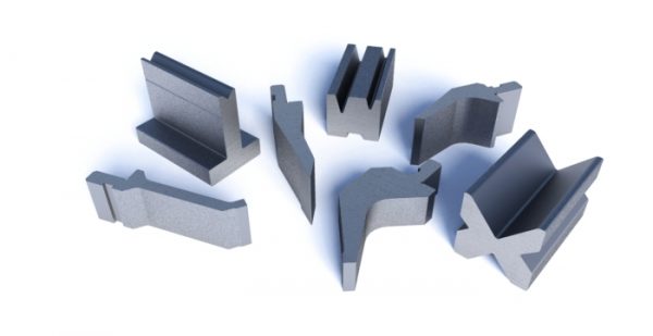
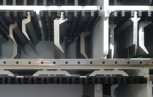
Figure 1
To get the most out of your press brake dies tools, the tangent of the bend, where the radius starts, ideally should be halfway down the die face. In this situation, half the die face is equal to the outside setback (OSSB), the distance from the outside mold line (planes that run parallel to the workpiece) to the tangent point of the bend.
Question:
Our fabrication department is documenting standard processes to select the correct die and punch combination to produce the desired results when air bending. We want to achieve a 90-degree bend for a 0.0751-in.-thick piece of 304 stainless steel with an inside bend radius that’s also 0.0751 in. There’s the 20 percent rule, and then there’s the 8x material thickness rule. How should I apply these rules to select a die opening?
Answer:
The 8x rule is an age-old rule of thumb based on 60,000-PSI-tensile cold-rolled steel that states it’s best practice to choose a die-opening width that’s eight times the material thickness. You generally get the best working results when working with the 8x rule. You ease forming and attain bend angle stability while working within tonnage requirements. You will find you can produce an inside radius approximately equal to the material thickness.
Still, “8x” is only a label, and the factor can increase or decrease with the material thickness. Sometimes the die-opening width equals 6x material thickness, other times 10x or 12x. The 8x rule is a good rule of thumb that keeps the tonnages low and the parts stable, at least to a point. But, unfortunately, it really doesn’t take different material types into account.
The 20 percent rule defines the floated inside radius in an air form over a given die. Unlike the 8x rule, the 20 percent rule can be factored for material type. In 304 stainless steel, the inside radius will be 20 to 22 percent of the die-opening width; for cold-rolled steel, the inside bend radius will be 15 to 17 percent; and for 5052 H32 aluminum, the inside bend radius will be 9 to 11 percent. You start with the median value (in the case of 304 stainless, this is 21 percent), then adjust if needed.
The 20 percent rule simply describes the resulting inside radius when air bending, and it’s used to calculate bend deductions. However, it usually isn’t a means of developing a die opening, because it doesn’t take into account springback or tonnage limits.
For your stainless steel job, you could rewrite the 20 percent rule formula—Width of die opening × 21 percent = Inside bend radius—to read Inside bend radius/21 percent = Width of die opening. This would give you: 0.075 in./0.21 = 0.357-in. die-opening width. But again, this does not take into account springback or tonnage limits, and it could seriously overload the press or the tooling. This is small for a die opening, and tonnage should be a consideration.
To achieve a certain radius, you need the right tooling and press brake. Ultimately, available die-opening widths in your tooling library, as well as tonnage capabilities of your tooling and press brakes, will determine the inside bend radii you can achieve when air bending a given material type and thickness. A tooling selection procedure for air bending should include the following:
1. Ensure that the specified inside bend radius is not less than the minimum sharp bend radius. If it isn’t, the inside bend radius can’t be achieved physically, short of stamping or bottoming. That’s because, when the bend turns sharp, the punch starts to dig a ditch into the material. For mild steel, a bend usually turns sharp when the inside radius reaches about 63 percent of material thickness. (For more on sharp bends, see How a bend turns sharp.) In your case, of course, you’re looking to achieve a ratio of 1-to-1 for material thickness to inside bend radius, which is certainly achievable, as long as your tooling and machines can handle the tonnage requirements.
2. Select the die opening. When it comes to any kind of machine, you generally do not want to overuse or underuse it. You get the most out of the machine at half of the maximum working value. That being said, isn’t the combination of the die, punch, and material really a “machine”? Of course it is. So what is half the working value of a die? Under perfect conditions, that point occurs halfway down the die face, as shown in Figure 1.
To find the geometrically perfect die opening—one in which the bend occurs halfway down the die face—use the following formula: (Outside bend radius × 0.7071) × Factor = Perfect die opening. (Editor’s note: For more detail behind this formula, visit www.thefabricator.com and type “Finding the perfect die opening” in the search bar.)
To calculate your outside bend radius, add the desired inside bend radius to the material thickness. So in your example, you would add 0.075-in. inside radius to the 0.075-in. material thickness and get an outside bend radius of 0.150 in.
The factor in the formula is a multiplier, and a multiplier of 4.0 would give you a value as close to geometrically perfect as possible, practically speaking, but with no allowance for springback. To account for springback, increase the multiplier slightly. In material thicknesses less than 0.125 in., a realistic working multiplier is 4.85. In material between 0.125 and 0.250 in., the multiplier is 5.85 in. (material more than 0.250 in. thick is calculated differently). This die selection method keeps the relationships consistent whether the radius is large and the material thin, or the material is thick and the radius small.
In your situation, you would calculate the following: (Outside bend radius × 0.7071) × Factor = Perfect die opening; or (0.150 in. × 0.7071) × 4.85 = 0.514 in. Of course, your shop probably doesn’t have a die-opening width of 0.514 in., so you’ll likely need to choose the closest width available, between a 0.472- in. or a 0.551 in. die. Choosing the closest available die opening will keep your inside bend radius as close as possible to the called value. This assumes that excess tonnage is not an issue if a smaller die is used.
(Note that using a factor of 4.0, the die width value would be 0.424 in., which, at least in the theoretical sense, is geometrically perfect for the job, but again does not take springback into consideration.)
3. Calculate the tonnage requirements. Now that you’ve determined the ideal die opening, you need to make sure it doesn’t exceed available tonnage of your press or tooling. To calculate this, use the following: [(575 × Material thickness2)/Die opening] × Material factor =Tonnage per foot.
We use the 60,000-PSI-tensile AISI 1035 (the most common type of cold-rolled steel used) as a baseline and so give it a material factor value of 1. To obtain a factor for a specific material, you can perform a simple comparison of tensile strengths, working with 60,000-PSI tensile as the baseline. If your 304 stainless is specified as having 85,000-PSI tensile, then you divide that tensile by 60,000 to get 1.4. So your tonnage calculation would be: [(575 × 0.005625) / 0.551] × 1.4 = 8.22 tons per foot. You will need to consider the length of the bend as well. If you’re within the tonnage limits of your tooling and press brake, then it’s on to the next step.
4. If the die width is acceptable, calculate the bend radius using the 20 percent rule. Start with the median value. Back to our 304 stainless example, the median percentage is 21. Multiply this percentage by the actual die opening you’ll be using, and you get the resulting inside bend radius: 0.551 in. × 0.21 = 0.1157-in. inside bend radius.
The actual radius will be approximately 0.116 in., which is as close to 1-to-1 as you can get in an air form. Yes, the radius is larger than a 1-to-1 ratio of bend radius to material thickness, but the die also is larger than perfect. Even a geometrically perfect die width would yield an inside radius slightly larger than the material thickness. Short of stamping, an exact 1-to-1 ratio is not possible without custom tooling.
5. Use this inside bend radius value to calculate the bend deduction. You now insert this inside bend radius value into your bend deduction formulas. Software has automated these calculations nowadays, but for a review of the math, check out “How the inside bend radius forms,” available at www.thefabricator.com.
6. Use the selected tool set to achieve the calculated bend deduction. You’ve determined that the inside bend radius is physically possible; you’ve selected a die-opening width that will get you as close as possible to the desired inside bend radius; you calculated your bend deductions based on the 20 percent rule; and you’ve taken available tonnage and springback into account. Considering all this, you’re well on your way to building perfect parts.
The press brake toolings are divided into two parts.
The toolings installed on the top of the ram are called punches, and the bottom toolings on the workbench are called dies.
The two parts work together on the metal plate to complete the bending of the workpiece.
The process that which the punch of the press brake exerts a force on the metal plate on the die is the bending process.
The upper die presses the metal plate through different power sources driving the ram.
The driving sources include mechanical, hydraulic, and servo motors.
Standards of Press Brake Toolings
There are different types of punches and dies.
The accuracy and efficiency of bending can be improved only by selecting the correct matching punches and dies for bending.
The standard size toolings are more convenient to replace. Because the design of tooling parts with standard dimensions is consistent.
In this way, there is no need to make too many adjustments when replacing the punches and dies. These toolings are kept in the same position to replace conveniently.
The upper parts of the ram of the press brake need a clamping device for fixing the punches.
The clamping can fix the punches in the required position. The punches bend the metal plate with the motion of the ram.
Die segmentation can facilitate the bending process of various sized workpieces. Press brake toolings require very high accuracy.
Especially the accuracy of punch tip and die shoulders. Cause these parts will directly contact the sheet metal during bending.
Moreover, the punches and dies with high precision can reduce the adjustment in the installation process.
Types of Punches and Dies
Press brake dies include V-die, U-die, and Z-die, and the most common is V-die. The minimum flange length shall be at least 4 times the material thickness.
Otherwise, the exact bending angle cannot be obtained. V-die sets with different opening widths match the corresponding punches.
In this way, the press brake can bend at different angles and different materials.
Press brake punches are mainly classified into three types: straight punch, gooseneck punch, and acute punch.
The die of the press brake can be divided into single V die, double V dies, and Multi-V die.
Consideration for Tooling Selection
Bending Material
First, the type of metal you want to bend is an important factor.
The thickness of the metal determines the die opening, bending radius, and bending angle.
For example, some steels have greater strength and higher resistance than other steels.
This resistance is the tensile strength(UTS) of the metal. The tensile strength of metals is different, which requires different strength molds.
In addition, it needs to be considered that the length of the metal plate determines how many toolings are required.
The V Opening and Radius of Material
When bending sheet metal, if the thickness and metal type are the same, there is not only one V-die opening size.
The sheet metal will not be lost during bending. If the internal radius is less than the thickness of the metal plate, the plate will be stretched, which will lead to the deformation of the workpiece. While a radius greater than the thickness of the sheet will not cause deformation.
When choosing the perfect V-die opening, we should not only avoid radius deformation but also choose a smaller radius.
The rule of 8
There is a rule of thumb applicable to the V-opening of press brake dies: the rule of 8.
The rule of 8 is based on 60000 PSI tensile cold-rolled steel. It stipulates that the V opening die shall be eight times the thickness of the bending material.
The rule of 8 applies to the most bending processes. Within the specified tonnage range, an internal radius approximately equal to the thickness of the material can be produced.
However, this is not a perfect law, because the factor will increase or decrease with the variation of the material thickness.
As a result, the width of some V-die openings is 6 times, 10 times, or even 12 times the thickness of the material.
The thicker plate is usually 10 times. Because thicker plates tend to lose some ductility.
So we use a larger V opening to distribute the force in a larger area and avoid cracks in the plate. Before determining the press brake dies, first determine the thickest and thinnest metal sheet to be bent.
Use the rule of 8 to determine the correct size of the V dies.
Select the smallest V to die and double its size to determine the next V die until the maximum mold is reached. If an exact match cannot be found, the dimensions should be rounded to the nearest available mold.
V opening affects the radius of bending material.
It is ideal on most bending materials when the internal radius equals 1 thickness. If the inner radius is less than 1 thickness, it means that the material extracted from the radius disappears.
In plate bending, if the inner radius is less than 1 thickness, we can see how the “side bulge” appears at the bending.
The larger the V-die opening, the larger the radius of the metal plate.
However, the tensile strength of the material will also affect the radius.
On a given V-die opening, the stronger the material, the greater the radius.
On mild steel, the bending radius (R) is usually 1 / 8 of the V-die opening, resulting in the following formula: R=V/8
This rule will vary for different metal types.
Minimum Length of the Flange or Leg
When selecting V-shape dies, pay attention to the flange length or leg required by the workpiece.
When bending, the sheet metal must always be in direct contact with the shoulder of the die.
Less than the specified flange length will fall into the V-shape opening.
If so, the bending result will be inaccurate.
Therefore, the larger the V-shape opening, the larger the minimum flange or leg on the metal plate.
The minimum flange formed by V-die is about 70% of the opening of the standard V-die.
The acute angle die can reach 110% or more of the V-die opening.
Before determining the minimum flange length, the sheet metal should be placed on the die.
In this way, the material contact on the die shoulder is equal to 20% of the V-die opening.
Correct tooling selection and material use can improve the accuracy of bending workpieces.
They will affect the bending angle, internal radius, minimum flange length, and the appearance of the whole workpiece.
Using the correct tooling can improve bending efficiency, reduce cost, prevent profile deformation, and protect the safety of press brake operators.
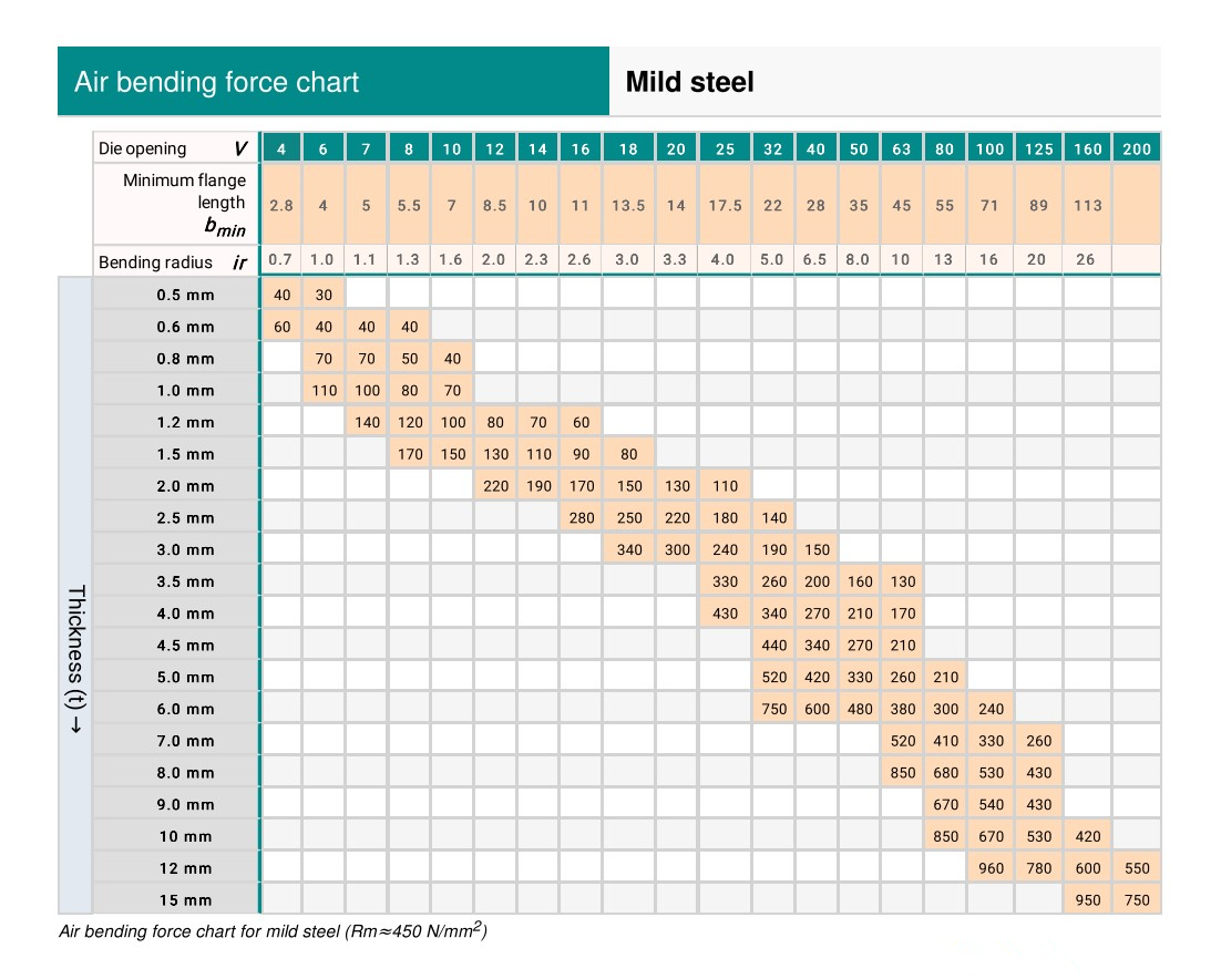
Air Bending Force Chart Background
The air bending force chart records the standard lower die V width and required bending force corresponding to the bending of different sheet metals, and has already become ageneral specification in the industry.
However, there was no such specification at the earliest time.Each press brakemanufacturer decided to use the V-width based on their own experience.
At that time, Amada collected and summarized the experience data of customers from allwalks of life around the world, and finally made the following most authoritative bendingforce chart for bending process.
Air Bending Force Chart-Mild Steel
Air Bending Force Chart-Stainless Steel
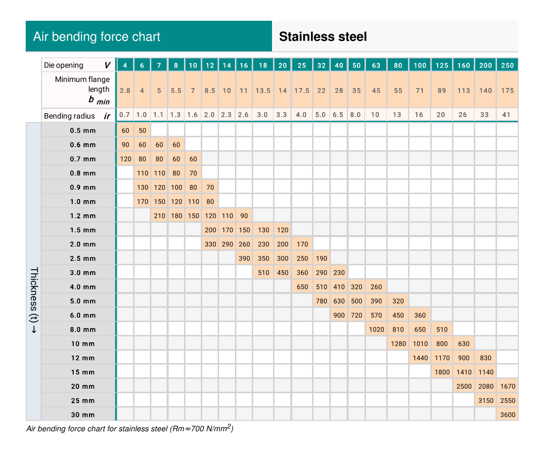
You can also use our press brake tonnage calculator to calculate the required bendingforce for your sheet metal products.
![]()