- Press brake toolings are made of high-quality steel products made by special heat treatment, with high hardness, not easy to wear and tear, able to bear great pressure, but each mold has its limits pressure: ton/meter, so choose the length of the mold when using the press brake toolings correctlyThat is, how much pressure per meter to bear, must not exceed the marked limit pressure.
- In order not to damage the die, we stipulate that align with the original point, it is necessary to use the upper and lower modes with the length of 300mm to do the alignment.The upper mold lower mold of the same height only can be used after the alignment.It is strictly forbidden to use the split small mold for the alignment, and the alignment must be based on the regulated pressure inside the press brake machine.
- In the use of the mould, due to the various height of the molds, the mold can only be used in a press brake machine with the same height, which can not be used in different heights.
- When using the press brake toolings, choose the right upper die and lower die according to the sheet metal hardness, thickness, and length.Generally, the slot width of the lower die should be 5-6 times the thickness of the metal plate, while the length should be longer than the sheet.The harder and the thickness of the sheet metal material, the wider of the lower die slot.
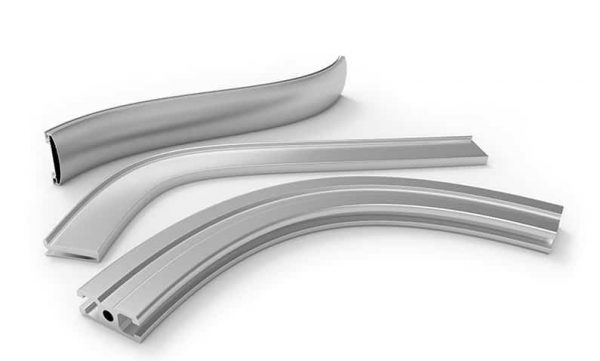
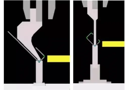
- When bending an acute angle or a dead angle, 30° punch should be chosen. Bending the acute angle first, then flattening.When bending R angle, R punch and R die should be chosen.

- In bending the long piece of work, it is better not to use a segmented mold in order to reduce the indentation at the mold connection position, and it is better to choose a single slot die, because the exterior angle R of lower die with single slot V is big, not easy to generate bending indentation.
- When selecting the top punch, we should know the type of die and the parameters well, and then decide which punch should be used based on the shape of the product that needs to be formed.
- When bending hard or too thick product, do not use press brake die to bend steel bar or other cylinder products.
- When using the press brake mold, the operators should have a clear mind.The upper die and lower die of press brake machine should be locked after alignment, in case the punch fall down to hurt the workers or damage the die.Attention should be paid when adding pressure during the operation process, do not add too much pressure and pay attention to the data changes on the display screen.
- After finish using the press brake toolings, put the die back in the press brake die cabinet (press brake store) according to the marking, clean the dust on the mold regularly, and apply the anti-rust oil to prevent rust which will reduce the precision of the toolings

Before discussing aluminum alloys, we should cover some background about the factors that affect their bendability. As you can imagine, products like aluminum foil, gutters, traffic signs, and automotive body parts, which are all made from aluminum alloys, have different bendability.
Three factors control the bendability of the various alloys in these products:
- The formability of the aluminum alloy
- Thickness and bend radius
- Percent elongation
Let’s have a deeper look at these factors!
1st Factor – Formability
Formability is the ability of a given material to experience permanent deformation without the forming process cracking or tearing it. Permanent deformation is also known as plastic deformation in the materials science world.
Generally speaking, formability is a relative term and not a specific value. For example, the applied force necessary to shape a product depends on more than just the strength and ductility of a material. It also depends on factors such as the shape of the part and the thickness of the starting material.
In other words, we can measure the forming force to produce a specific part from a particular starting material. However, changing the shape of the part or the physical properties of the starting material will change the amount of force that needs to be applied.
2nd Factor – Thickness and Bend Radius
If you’ve handled regular aluminum foil, you’ll know that it is effortless to bend. However, if you had to bend a sheet of aluminum that was one-thousand times thicker than aluminum foil, it would be much harder! That is because the thicker a material is, the more difficult it is to bend.
You can also bend an aluminum gutter with your bare hands. But if you try to bend it to a tight angle without breaking it, you will have a hard time! Bending metal to a small bend radius has the potential to cause tearing or cracking.
The Fabricator offers certain key tables and general rules which are helpful for understanding the limits to bendability for specific aluminum alloys. You can use these to determine the minimum allowable bend radius for particular thicknesses of aluminum sheet.
3rd Factor – Percent Elongation
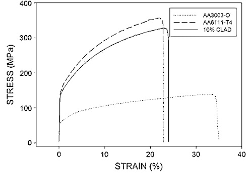
Percent elongation represents the ability of the material to be plastically deformed under tension. It is also known as plastic strain or stain applied beyond the yield strength limit of a material.
The more ductile aluminum alloys can experience more significant plastic deformation with small increases in applied stress. This results in better overall aluminum bendability.
Like the other properties, the percent elongation varies for each alloy. Take a look at the stress-strain curve above. You’ll see that annealed aluminum alloy 3003 (shown as AA3003-O) has a very high percent elongation (strain %) of roughly 35%. It has very high bendability relative to other alloys.
3 of the Best Aluminum Alloys for Bending
Numerous metal alloying agents can be combined with aluminum to produce different aluminum alloys. The system for naming them uses four digits, with the first digit representing their chemical composition. We explain this in our article on aluminum alloy designations and tempers.
Generally speaking, aluminum alloys from the 1XXX, 3XXX, and 5XXX series demonstrate better bendability than other aluminum alloys. Some 6XXX series alloys are fairly bendable as well.
However, the different properties offered by each may make some more desirable than others. For example, 1XXX series aluminum generally has poor mechanical properties and is not suited to structural applications.
Now let’s discuss which alloys offer the best bendability and when you should use them.
#1 – Aluminum Alloy 3003
This alloy is primarily alloyed with manganese and is one of the most commonly used aluminum alloys for bending applications. It has excellent formability properties and does not require heat to be bent or molded.
Companies often make gutters, roofing, siding, chemical equipment, and storage tanks from 3003 aluminum.
#2 – Aluminum Alloy 5052
With magnesium as the primary alloying element, AA5052 demonstrates moderate-to-high strength characteristics. At the same time, it retains good bendability, and designers can use it for more intensive applications than AA3003. The corrosion resistance of this alloy is also excellent against seawater, meaning it is excellent for applications in marine equipment.
Manufacturers often produce hydraulic tubes, traffic and hardware signs, medical equipment, marine equipment, and electronics (chassis and enclosures).
#3 – Aluminum Alloy 6061
You will find this is an extremely common alloy in your day-to-day life. Even though it is not as bendable or formable as the two alloys above, it is the strongest among all three. It has magnesium and silicon as alloying elements, and you can further enhance its strength with heat treatment.
Alloy 6061 is widely referred to as “structural aluminum” because it is so commonly used in structural (construction) applications. Nevertheless, due to its outstanding properties, it is also used in food and beverage containers, ladders, aircraft and automotive parts, scuba tanks, bicycle frames, and more.
Why Are These 3 Alloys Important?
Despite their different properties, these alloys are excellent examples of bendability in aluminum alloys. They demonstrate that even though some aluminum alloys feature better formability and percent elongation for a given bend radius and thickness, they each serve a unique purpose and a wide variety of applications.
Even with slightly lower bendability, the strength of alloy 6061 makes it one of the most widely used aluminum alloys. In the same way, alloy 3003 has multiple uses in applications that require superior bendability. Meanwhile, alloy 5052 is commonly used thanks to its balance in terms of bendability and strength.
Explanation of aluminum plate grade
1000 series representative
1050, 1060, 1070, 1000 series aluminum plate is also called pure aluminum plate.Among all series, 1000 series belongs to the series with the most aluminum content.The purity can reach more than 99.00%.
Because it does not contain other technical elements, the production process is relatively single and the price is relatively cheap.It is the most commonly used series in conventional industry at present.At present, most of the products in circulation in the market are 1050 and 1060 series.
The minimum aluminum content of the 1000 series aluminum plate is determined according to the last two Arabic numerals. For example, the last two Arabic numerals of the 1050 series are 50.According to the international brand naming principle, the aluminum content must reach 99.5%, and the above is regarded as qualified products.China’s aluminum alloy technical standard (GB / t3880-2006) also clearly stipulates that the aluminum content of 1050 must reach 99.5%.Similarly, the aluminum content of 1060 series aluminum plates must reach more than 99.6%.
1000 series typical brand and application:Pure aluminum plate 1060 is mainly used in occasions requiring high corrosion resistance and formability, but for parts with low strength, such as chemical equipment, marine equipment, railway oil tank car, conductor materials, instrument materials, welding rods, etc.
2000 series aluminum plate representative
2A16 (LY16), 2A06 (LY6) and 2000 series aluminum plates are characterized by high hardness, of which the original content of copper is the highest, about 3-5%.
2A12 aluminum alloy is a kind of high strength hard aluminum, which can be strengthened by heat treatment; 2A12 aluminum alloy has good spot weldability and tends to form intergranular cracks when gas welding and argon arc welding are used;
2A12 aluminum alloy has good machinability after cold work hardening.
The corrosion resistance is not high. Anodizing and painting methods or aluminum coating on the surface are often used to improve corrosion resistance.
2000 series aluminum plate belongs to aviation aluminum material, which is not often used in conventional industry at present.
At present, there are few manufacturers producing 2000 series aluminum plates in China.The quality cannot be compared with that of foreign countries.
At present, imported aluminum plates are mainly provided by Korean and German manufacturers.With the development of China’s aerospace industry, the production technology of 2000 series aluminum plate will be further improved.
3000 series aluminum plate representative
3000 series aluminum plates are mainly represented by 30033003 and 3A21. It can also be called antirust aluminum plate.The production process of 3000 series aluminum plate in China is excellent. 3000 series aluminum plate is mainly composed of manganese.The content is between 1.0-1.5. It is a series with good antirust function.It is commonly used in humid environments such as air conditioner, refrigerator and underbody. The price is higher than 1000 series. It is a more commonly used alloy series.
3000 series typical grade and its application:
3003 aluminum is mainly used for processing parts requiring good molding performance, high corrosion resistance, or good weldability, or workpieces requiring higher strength than 1000 series alloy, such as tanks and tanks for transporting liquid, pressure tanks, storage devices, heat exchangers, chemical equipment, aircraft fuel tanks, oil duct, reflective plates, kitchen equipment, washing machine cylinder block, rivet, welding wire.
3004 aluminum requires higher parts than 3003 alloy, chemical product production and storage devices, sheet processing parts, building baffles, cable ducts, sewers and various lamp parts.
4000 series aluminum plate representative
The 4000 series aluminum plate represents the 4a014000 series aluminum plate, which belongs to the series with high silicon content.
Generally, the silicon content is between 45-6.0%.It belongs to building materials, mechanical parts, forging materials and welding materials; Low melting point and good corrosion resistance.Product features: heat resistance and wear resistance.
5000 series representative
The 5000 series represents 5052, 5005, 5083 and 5A05 series.
5000 series aluminum plate belongs to the commonly used alloy aluminum plate series.The main element is magnesium, and the magnesium content is between 3-5%. It can also be called aluminum magnesium alloy.The main features are low density, high tensile strength and high elongation.
Under the same area, the weight of aluminum-magnesium alloy is lower than that of other series, so it is often used in aviation, such as aircraft fuel tank.
It is also widely used in conventional industry. The processing technology is continuous casting and rolling, which belongs to the hot-rolled aluminum plate series, so it can do deep oxidation processing.
In China, the 5000 series aluminum plate is one of the more mature aluminum plate series.
5000 Series typical grade and its application:
5052 aluminum has good forming and processing performance, corrosion resistance, weldability, fatigue strength and medium static strength. It is used to manufacture aircraft fuel tank, oil pipe, sheet metal parts, instruments, street lamp supports, rivets, wires, etc.
6000 series representative
6061 mainly contains magnesium and silicon, so it integrates the advantages of 4000 series and 5000 series.
6061 is a cold-treated aluminum forging product, which is suitable for applications requiring high corrosion resistance and oxidation resistance.
Good usability, excellent interface characteristics, easy coating and good processability.
It can be used for low-pressure weapons and aircraft joints.
General features of 6061: excellent interface features, easy coating, high strength, good usability and corrosion resistance.
Typical uses of 6061 aluminum: aircraft parts, camera parts, couplers, ship accessories and hardware, electronic accessories and connectors, decorative or various hardware, hinge head, magnetic head, brake piston, hydraulic piston, electrical accessories, valves and valve parts.
7000 series representative
7075 mainly contains zinc. It also belongs to Aviation series. It is aluminum magnesium zinc copper alloy, heat treatable alloy, superhard aluminum alloy and has good wear resistance.
7075 aluminum plate is stress relieved and will not deform and warp after processing.
All super large and super thick 7075 aluminum plates are detected by ultrasonic, which can ensure that there are no sand holes and impurities.
7075 aluminum plate has high thermal conductivity, which can shorten the forming time and improve the work efficiency.
7075 is mainly characterized by hardness.
7075 is a high hardness and high strength aluminum alloy, which is commonly used in the manufacture of aircraft structure and futures.
It requires the manufacture of high stress structural parts and molds with high strength and strong magic corrosion resistance.
At present, it basically depends on imports, and China’s production technology needs to be improved.
8000 Series
The more commonly used 8011 belongs to other series.
In my memory, it is an aluminum plate whose main function is to make a bottle cap. It is also used in radiators. Most applications are aluminum foil, which is not commonly used.
Figure 1
To get the most out of your press brake dies tools, the tangent of the bend, where the radius starts, ideally should be halfway down the die face. In this situation, half the die face is equal to the outside setback (OSSB), the distance from the outside mold line (planes that run parallel to the workpiece) to the tangent point of the bend.
Question:
Our fabrication department is documenting standard processes to select the correct die and punch combination to produce the desired results when air bending. We want to achieve a 90-degree bend for a 0.0751-in.-thick piece of 304 stainless steel with an inside bend radius that’s also 0.0751 in. There’s the 20 percent rule, and then there’s the 8x material thickness rule. How should I apply these rules to select a die opening?
Answer:
The 8x rule is an age-old rule of thumb based on 60,000-PSI-tensile cold-rolled steel that states it’s best practice to choose a die-opening width that’s eight times the material thickness. You generally get the best working results when working with the 8x rule. You ease forming and attain bend angle stability while working within tonnage requirements. You will find you can produce an inside radius approximately equal to the material thickness.
Still, “8x” is only a label, and the factor can increase or decrease with the material thickness. Sometimes the die-opening width equals 6x material thickness, other times 10x or 12x. The 8x rule is a good rule of thumb that keeps the tonnages low and the parts stable, at least to a point. But, unfortunately, it really doesn’t take different material types into account.
The 20 percent rule defines the floated inside radius in an air form over a given die. Unlike the 8x rule, the 20 percent rule can be factored for material type. In 304 stainless steel, the inside radius will be 20 to 22 percent of the die-opening width; for cold-rolled steel, the inside bend radius will be 15 to 17 percent; and for 5052 H32 aluminum, the inside bend radius will be 9 to 11 percent. You start with the median value (in the case of 304 stainless, this is 21 percent), then adjust if needed.
The 20 percent rule simply describes the resulting inside radius when air bending, and it’s used to calculate bend deductions. However, it usually isn’t a means of developing a die opening, because it doesn’t take into account springback or tonnage limits.
For your stainless steel job, you could rewrite the 20 percent rule formula—Width of die opening × 21 percent = Inside bend radius—to read Inside bend radius/21 percent = Width of die opening. This would give you: 0.075 in./0.21 = 0.357-in. die-opening width. But again, this does not take into account springback or tonnage limits, and it could seriously overload the press or the tooling. This is small for a die opening, and tonnage should be a consideration.
To achieve a certain radius, you need the right tooling and press brake. Ultimately, available die-opening widths in your tooling library, as well as tonnage capabilities of your tooling and press brakes, will determine the inside bend radii you can achieve when air bending a given material type and thickness. A tooling selection procedure for air bending should include the following:
1. Ensure that the specified inside bend radius is not less than the minimum sharp bend radius. If it isn’t, the inside bend radius can’t be achieved physically, short of stamping or bottoming. That’s because, when the bend turns sharp, the punch starts to dig a ditch into the material. For mild steel, a bend usually turns sharp when the inside radius reaches about 63 percent of material thickness. (For more on sharp bends, see How a bend turns sharp.) In your case, of course, you’re looking to achieve a ratio of 1-to-1 for material thickness to inside bend radius, which is certainly achievable, as long as your tooling and machines can handle the tonnage requirements.
2. Select the die opening. When it comes to any kind of machine, you generally do not want to overuse or underuse it. You get the most out of the machine at half of the maximum working value. That being said, isn’t the combination of the die, punch, and material really a “machine”? Of course it is. So what is half the working value of a die? Under perfect conditions, that point occurs halfway down the die face, as shown in Figure 1.
To find the geometrically perfect die opening—one in which the bend occurs halfway down the die face—use the following formula: (Outside bend radius × 0.7071) × Factor = Perfect die opening. (Editor’s note: For more detail behind this formula, visit www.thefabricator.com and type “Finding the perfect die opening” in the search bar.)
To calculate your outside bend radius, add the desired inside bend radius to the material thickness. So in your example, you would add 0.075-in. inside radius to the 0.075-in. material thickness and get an outside bend radius of 0.150 in.
The factor in the formula is a multiplier, and a multiplier of 4.0 would give you a value as close to geometrically perfect as possible, practically speaking, but with no allowance for springback. To account for springback, increase the multiplier slightly. In material thicknesses less than 0.125 in., a realistic working multiplier is 4.85. In material between 0.125 and 0.250 in., the multiplier is 5.85 in. (material more than 0.250 in. thick is calculated differently). This die selection method keeps the relationships consistent whether the radius is large and the material thin, or the material is thick and the radius small.
In your situation, you would calculate the following: (Outside bend radius × 0.7071) × Factor = Perfect die opening; or (0.150 in. × 0.7071) × 4.85 = 0.514 in. Of course, your shop probably doesn’t have a die-opening width of 0.514 in., so you’ll likely need to choose the closest width available, between a 0.472- in. or a 0.551 in. die. Choosing the closest available die opening will keep your inside bend radius as close as possible to the called value. This assumes that excess tonnage is not an issue if a smaller die is used.
(Note that using a factor of 4.0, the die width value would be 0.424 in., which, at least in the theoretical sense, is geometrically perfect for the job, but again does not take springback into consideration.)
3. Calculate the tonnage requirements. Now that you’ve determined the ideal die opening, you need to make sure it doesn’t exceed available tonnage of your press or tooling. To calculate this, use the following: [(575 × Material thickness2)/Die opening] × Material factor =Tonnage per foot.
We use the 60,000-PSI-tensile AISI 1035 (the most common type of cold-rolled steel used) as a baseline and so give it a material factor value of 1. To obtain a factor for a specific material, you can perform a simple comparison of tensile strengths, working with 60,000-PSI tensile as the baseline. If your 304 stainless is specified as having 85,000-PSI tensile, then you divide that tensile by 60,000 to get 1.4. So your tonnage calculation would be: [(575 × 0.005625) / 0.551] × 1.4 = 8.22 tons per foot. You will need to consider the length of the bend as well. If you’re within the tonnage limits of your tooling and press brake, then it’s on to the next step.
4. If the die width is acceptable, calculate the bend radius using the 20 percent rule. Start with the median value. Back to our 304 stainless example, the median percentage is 21. Multiply this percentage by the actual die opening you’ll be using, and you get the resulting inside bend radius: 0.551 in. × 0.21 = 0.1157-in. inside bend radius.
The actual radius will be approximately 0.116 in., which is as close to 1-to-1 as you can get in an air form. Yes, the radius is larger than a 1-to-1 ratio of bend radius to material thickness, but the die also is larger than perfect. Even a geometrically perfect die width would yield an inside radius slightly larger than the material thickness. Short of stamping, an exact 1-to-1 ratio is not possible without custom tooling.
5. Use this inside bend radius value to calculate the bend deduction. You now insert this inside bend radius value into your bend deduction formulas. Software has automated these calculations nowadays, but for a review of the math, check out “How the inside bend radius forms,” available at www.thefabricator.com.
6. Use the selected tool set to achieve the calculated bend deduction. You’ve determined that the inside bend radius is physically possible; you’ve selected a die-opening width that will get you as close as possible to the desired inside bend radius; you calculated your bend deductions based on the 20 percent rule; and you’ve taken available tonnage and springback into account. Considering all this, you’re well on your way to building perfect parts.
Air Bending Force Chart Background
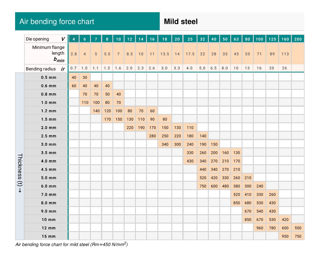
The air bending force chart records the standard lower die V width and required bending force corresponding to the bending of different sheet metals, and has already become ageneral specification in the industry.
However, there was no such specification at the earliest time.Each press brakemanufacturer decided to use the V-width based on their own experience.
At that time, Amada collected and summarized the experience data of customers from allwalks of life around the world, and finally made the following most authoritative bendingforce chart for bending process.
Air Bending Force Chart-Mild Steel
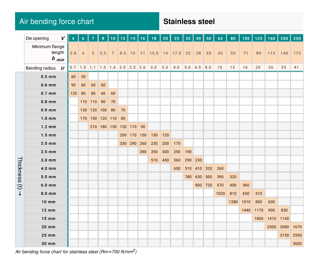
Air Bending Force Chart-Stainless Steel
You can also use our press brake tonnage calculator to calculate the required bendingforce for your sheet metal products.
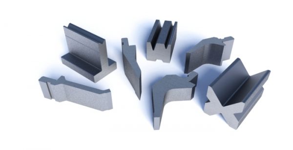
The press brake dies(toolings) are very important to the sheet metal producer,they are the key parts for press brake machine,this article briefly introduce how to to choose press brake dies(toolings)
The different dies should be used for fabricating different workpieces. You need to know the fabrication parameters of the press brake machine as well as the die very well, then it is possible for you to choose the right press brake die to match each other.The parameters of press brake including stroke, working ability, daylight (open height),middle plate type.
A.How to choose press brake parameters
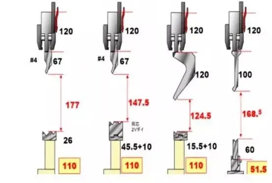
Press brake die height formula
– Stroke (mm)=daylight – middle plate height – upper die height – lower die height -(lowerdie height – 0.5V+t) t = plate thickness (mm)
Given: daylight 370mm, max stroke 100mm
Reach: stroke = 370-120-70-75-(26-0.5*8+t)= (83-t)mm
Note: 0.5V < stroke < max stroke
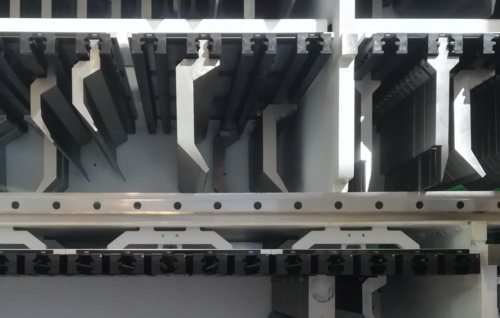
Please note the lower die base also have many different heights, which is used fordifferent fabrication purpose.So don’t forget this when choosing lower die base.
Different tool & die cluster can obtain different combined height for different fabricationpurposes of parts.
B.How to choose press brake dies parameters
Upper die shank type
Upper die shank has three types to match different middle plate.
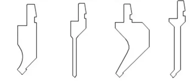
Upper die shape
Common standard upper die:
Upper die tip radius & top angle
Common upper die tip radius including:
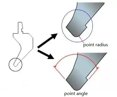
(1)0.2R (2)0.6R (3)0.8R (4)1.5R (5)3.0R
How to choose proper press brake die tip radius: choose 0.6R for plate thickness
Standard upper die tip angle including: 90°,88°,86°,60°,45°,30°, etc.
The dihedral angle of the die should less than the fabrication angle.
For example, if the workpiece’s bending angle is 90° , you should choose the die with 88° tipangle.
Lower die type
Generally, the lower die has a single V type and double V type, among which it is separatedinto the separated die and full-length die.
The different die is applied to a different fabricating purpose.
However, the single-V die has a much wider application than double-V die, while theseparated die is more widely used than full-length die.
Lower die V width (die opening), V groove angle
V groove choosing & plate thickness (T):
| T | 0.5-2.6 | 3-8 | 9-10 | ≥12 |
|---|---|---|---|---|
| V | 6*T | 8*T | 10*T | 12*T |
The V angle of the lower die is the same as upper die’s angle.
| PLATE THICKNESS | ≤0.6 | 1 | 1.2 | 1.5 | 2 | 2.5 | 3 |
| DIE WIDTH | 4 | 6 | 8 | 10 | 12 | 16 | 18 |
ln order to choose small V die for bending purpose in some special case, the spread ofevery punch should increase 0.2mm
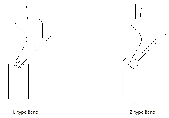
Min bending size
Normally min bending size:
一L-type: slot width/2+ plate thickness
一Z-type: slot width/2 + plate thickness* 2
Reference Value
| L-Type | 4.0 | 4.5 | 5.0 | 6.0 | 8.0 | 10.5 | 12.0 |
| Z-Type | 5.0 | 5.5 | 6.0 | 8.0 | 10.0 | 13.0 | 15.0 |
A lot of press brake operators get very confused when they’re setting the stroke data (orthe Y-axis data) in the press brake controller, especially for the old type press brake.Theydon’t know what exactly press brake stroke they should set, so the only way to solve theproblem is by testing again and again.
Definitely, this is not the right way.
Here SMBC will show you how to calculate press brake stroke length with exact formula.
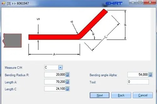
Firstly, please see below the schematic diagram.l will take the data on it as an example.
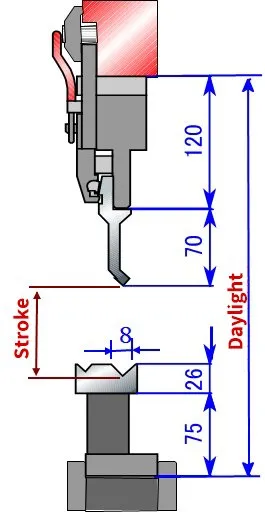
And the formula to calculate press brake stroke is:
Stroke = Daylight -Middle Plate Height – Punch Height – Die Base Height -(Die Height – 0.5V + t)
How to Calculate Press Brake Machines Tonnage? For determining the hydraulic bending force or the tonnage of the press brake that is required to bend the sheet metal in a specific thickness you have totally the following TWO methods:
By the press brake tonnage chart
By the bending force calculation formula
Only after the tonnage of the press brake confirmed, then you can spend your time taking other factors (press brakecomponents, toolings, controllers, etc) into consideration before making your decision to purchase the press brake.In this article, we will show you how to determine the required bending force by your sheet metal.
1.Press Brake Tonnage Chart
The following press brake tonnage chart is used by many press brake manufacturers both in China and abroad countries.
We know that many press brake suppliers are using a different chart, but most of them are similar and the final resultwill almost the same. So just take one of them as your reference.
Note: if there are no special requirements for the bending radius, the slot width v should be 8-10 times plate thickness.The tonnage as shown in the above press brake tonnage chart is calculated based on the sheet metal with the tensilestrength ob=450N/mm2 and length L=1m.
Now you have the bending force chart, the question is how to find the press brake tonnage in the above chart?
First,you need to know what does “s””V”“B”“R”means in the above chart. Check out the following pictures you will understand what do they mean.
- P= Bending force
- S = Thickness of sheet
- V = Vee opening of the bottom die
- B = Min bending flange
- R = Inner radius
If the thickness of your metal sheet S =4mm, generally the vee opening of the bottom die is 8 times the thickness of the sheet.However, for the thicker plate, the vee opening should be bigger.The following recommend vee opening of the bottom die can be your reference.
| S | 0.5-3mm | 3-8mm | 9-10mm | >12mm |
|---|---|---|---|---|
| V | 6S | 8S | 10S | 12S |
Now we back to the chart, find the S data in the chart which is “4” ,and now we know the “”V” should be 4*8=32.And you can see that the intersection of the row and column where the “s” and v”stay is “330” . The unit of”330”is“KN”.
Now we know that for bending the sheet metal with 4mm thickness and 1m length, the required tonnage is 330KN.lf bend the 4mm sheet in 3 meters, then the tonnage should be 330*3=990KN, which equals to 101 Ton.
Here we come to the conclusion: you should choose at least 100ton press brake. However, we recommend you tochoose the bigger tonnage like 120Ton because if the press brake works in full load for a long time, the service life of the machine will be shortened.
2.Bending Force Calculation Formula
For example:
Plate thickness S=4mm, width L=3m, ob=450N/mm2 Generally slot width V=S*8
Therefore P=650*4*4*3/4*8=975(KN)= 99.5(Ton)
The result is very close to the data in the bending force chart.
As you can see, method #1 to calculate the press brake tonnage is based on the mild steel material.What if the material is stainless steel, aluminum or brass?
lt’ s simple, multiply the results calculated by the above formula by the coefficients in the following table:
| Material | Mild steel | Stainless steel | Aluminum | Brass |
|---|---|---|---|---|
| Coefficients | 1 | 1.6 | 0.65 | 0.5 |
#2.Formula
Another press brake tonnage calculation formula is: P=1.42obS*L/v
P: bending force (KN)
S: plate thickness (mm)
L: plate width(m)
V: bottom die slot width (mm)
ob: tensile strength (Mpa)
For example:
Plate thickness S=4mm, width L=3m, ob=450N/mm2,Generally slot width V=S*8
Therefore P=1.42*450*4*4*3/4*8=958.5(KN)= 96 (Ton) For bending the sheet metal with different materials, the key point is to find out the tensile strength of the specific material, then you will get the required bending force by the above formula.
The tensile strength table below can be the reference:
| Material | Soft(N/mm2) | Hard(N/mm2) |
|---|---|---|
| Lead | 25-40 | — |
[/fusion_table][fusion_text columns=”” column_min_width=”” column_spacing=”” rule_style=”default” rule_size=”” rule_color=”” class=”” id=””]
| Tin | 40-50 | |
| Aluminum | 93 | 1710 |
| Aluminum Alloy Type 4 | 230 | 480 |
| Duralumin | 260 | 480 |
| Zinc | 150 | 250 |
| Copper | 220-280 | 300-400 |
| Brass(70:30) | 330 | 530 |
| Brass(60:40)) | 380 | 490 |
| Phosphor Bronze/Bronze | 400-500 | 500-750 |
| Nickel Silver | 350-450 | 550-700 |
| Cold Rolled Iron | 320-380 | |
| Steel .1% Carbon | 320 | 400 |
| Steel .2% Carbon | 400 | 500 |
| Steel .3% Carbon | 450 | 600 |
| Steel .4% Carbon | 560 | 720 |
| Steel .6% Carbon | 720 | 900 |
| Steel .8% Carbon | 900 | 1100 |
| Steel 1.0% Carbon | 1000 | 1300 |
| Silicon Steel | 550 | 650 |
| Stainless Steel | 650-700 | |
| Nickel | 440-500 | 570-630 |
![]()