
What Is Press Brake Crowning
To guarantee accurate, repeatable forming results, it’s essential to compensate for the deflection that inherently occurs in the beam (ram) and table of the press brake when load is applied. Without deflection compensation, it’s likely that a workpiece will have some form of deformation at its center when it’s bent along the full length of the press brake. This is especially so for press brakes 8 feet or longer, 80 tons or more, and when bending long or large parts, but it also can be the case when forming shorter workpieces. To keep the bend angle consistent over the full length of the part, Therefore, it is necessary to take corresponding measures to reduce or eliminate the deflection caused by the deformation.The so-called deflection compensation device we call it crowning has preset a deformation in the direction of the opposite force-deformation in the ram and the upper die or the worktable and the lower die working table, and the deformation has the same amount of deformation generated in the actual work.a press brake needs a crowning system, either in the beam, in the table, or in both.
In this age of short batches, complex parts, and quick turnaround, crowning ensures efficiency, part accuracy, and repeatability. In high-tonnage applications, crowning helps produce straight bends in challenging, high-tensile-strength materials.
Types of press brake crowning
Hydraulic Crowning
The hydraulic automatic deflection Crowning mechanism of the workbench is composed of a group of oil cylinders installed in the lower workbench. The position and size of each Crowning oil cylinder are designed according to the deflection ram of the ram and the workbench finite element analysis. The hydraulic crowning realizes the bulge Crowning of the neutral version through the relative displacement between the front, middle and back three vertical plates. The principle is that the bulge is realized through the elastic deformation of the steel plate itself, so the Crowning amount can be adjusted within the elastic range of the workbench.
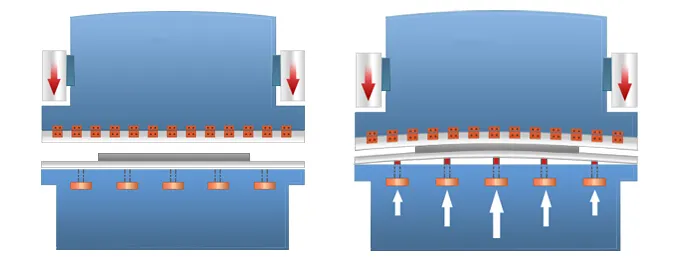
When the ram is down, the auxiliary cylinder is filled with liquid oil and goes downward.
During the bending process, hydraulic oil inlet into the auxiliary cylinder, so that the ram generate downward deflection for compensation.
Install the auxiliary hydraulic cylinder in the lower part of the worktable.
During the bending process, it generates an upward force on the worktable, which forms the automatic crowning system.
The pressure compensation device is composed of several small oil cylinders, comprising an oil cylinder, a motherboard, an auxiliary plate and a pin shaft, and a compensating cylinder is placed on the worktable.
The pressure compensation system is formed with a proportional relief valve.
During working, the auxiliary plate supports the oil cylinder, the oil cylinder holds up the motherboard up, just overcomes the deformation of the ram and the worktable.
The convex device is controlled by a numerical control system, so that the preload can be determined according to the thickness of the plate, the opening of the die and the tensile strength of the material when bending different sheet materials.
The advantage of hydraulic crowning is that it can realize the deflection compensation for continuous variable deformation with large compensation flexibility, but there are also some disadvantages of complex structure and in relatively high cost.
Mechanical Crowning
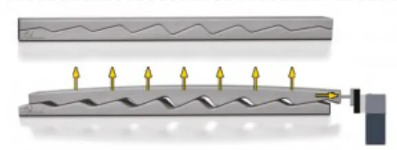
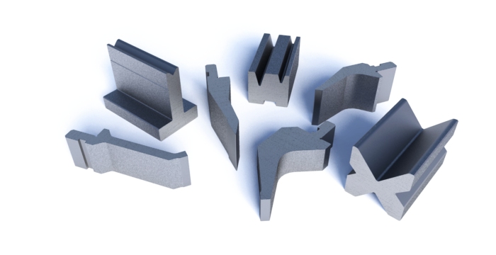
Mechanical crowning is a kind of new deflection compensation method, which generally uses a triangular oblique wedge structure.
The principle is that the two-triangle wedge block with α angles, the upper wedge moving is fixed at X-direction and can only move in Y-direction.
When the wedge moves the △x distance along the X-direction, the upper wedge moves up the H distance under the lower wedge force.
Regarding the existing mechanical compensation structure, two bolster plates are placed in full length on the worktable, the upper and lower plates are connected through the disc spring and bolts.
The upper and lower plates are consist of a number of oblique wedges with different slopes, through the motor drive to make them relatively moving and forming an ideal curve for a set of convex positions.
Leave A Comment