
Determining the bending radius of sheet metal is crucial to ensure successful and accurate bending operations without causing damage to the material. The bending radius is the minimum radius at which a sheet metal part can be bent without cracking or deforming. To calculate the bending radius, follow these steps:
1.Material Properties:
Gather information about the material you’re working with, such as its type (aluminum, steel, etc.) and its mechanical properties, including tensile strength, yield strength, and elongation.To avoid crack formation or part deformation while bending, it’s essential to adhere to minimum bend radius guidelines. These guidelines can vary based on the material and its properties:
- Mild Steel: For materials with a thickness up to 1.2 mm, a minimum bend radius of 0.8T (T = material thickness) is recommended.
- Aluminum: A minimum bend radius of 2T is typically suggested for materials below 4 mm thickness.
- Stainless Steel: For thicknesses up to 3 mm, a minimum bend radius of 1.5T is proposed.
These are general guidelines, and it’s crucial to consult material-specific recommendations or experiment with your specific sheet metal and tooling combinations to achieve the desired outcome. By adhering to appropriate bend radius guidelines, you can ensure a high-quality end product with fewer defects, less waste, and increased strength.
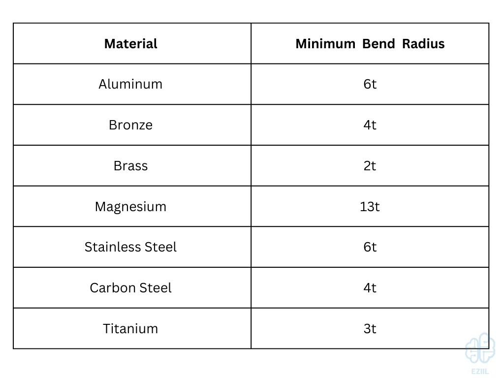
There is a minimum bending radius that should always be maintained in sheet metal design practices, and this minimum BR is displayed as a multiple of the specific raw material’s thickness. This value changes based on the type of material being bent as well.
See below for details:
2.Sheet Thickness:
Measure the thickness of the sheet metal accurately. This is an important factor in calculating the bending radius.
A simple and rough method to determine the bending radius is:
- If the plate thickness is less than 6mm, the bending radius can be equal to the plate thickness.
- If the plate thickness is between 6mm and 12mm, the bending radius is typically 1.25 to 1.5 times the plate thickness.
- If the plate thickness is greater than or equal to 12mm, the bending radius is typically 2 to 3 times the plate thickness.
Experience in actual sheet metal processing shows that when the plate thickness is generally no more than 6mm, the inner radius of sheet metal bending can directly use the plate thickness as the radius.
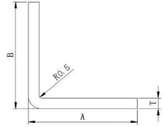
When the bending radius is r = 0.5, the general sheet metal thickness t is equal to 0.5mm.
If a bending radius different from the plate thickness is required, a special die must be used for processing.
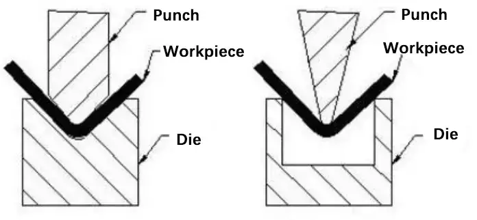
When the sheet metal drawing calls for a 90-degree bend with a particularly small bending radius, the sheet metal should first be grooved and then bent.
Special press brake tooling, such as punches and dies, can also be used.
The relationship between the bending radius of sheet metal and the width of the lower die groove of the bending die has been established through numerous experiments in sheet metal processing.
For example, when a 1.0mm plate is bent with an 8mm groove width, the ideal bending radius is R1.
If the groove width is increased to 20mm, the depth of the stretched plate increases, resulting in a larger tensile area and a larger R angle.
To avoid damaging the press brake die and to maintain the desired bending radius, it is recommended to bend with a narrow groove, following the standard ratio of 1:8 between plate thickness and groove width.
The minimum recommended ratio is 1:6 and bending with a ratio of less than 1:4 is not recommended.
Suggestion: If the strength allows, it is preferable to groove first and then bend in order to achieve a small sheet metal bending radius.
The following figure is a table provided by the press brake manufacturer, which shows the corresponding relationship between bending radius, pressure, and minimum bending height.
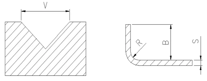
- V – bend notch width
- R – bend radius
- B – minimum bending height
- S – sheet thickness
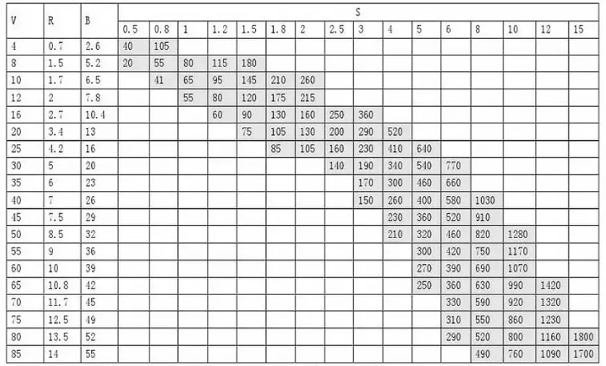
Note: The data with gray scale in the table represents the required bending pressure P (KN/m), and the maximum bending force of the press brake machine is 1700KN. There are five available bending knife edges: V = 12, 16, 25, 40, and 50.
Please refer to your available knife edge and bending length to determine the bending radius, which will help you calculate the accurate length of the material to be unfolded.
The above information pertains to the pressure parameters and bending die width of a single press brake.
The actual calculations should be based on the pressure and bending die of your own sheet metal processing facility.
3.Bend Angle:
Determine the desired angle of the bend. This will influence the bending radius as well.
4.Bend Radius Calculation:
There are a few different methods you can use to calculate the bending radius, depending on the specific circumstances. Here are two common approaches:
a. Formula Method:
Using the formula for the minimum bend radius based on the material’s properties:
Minimum Bend Radius (R) = (K * Thickness) / (Tensile Strength / Yield Strength)
Where:
- K is a constant typically ranging from 0.33 to 0.5 (it varies based on factors like material type, hardness, and temper).
- Thickness is the thickness of the sheet metal.
- Tensile Strength is the maximum amount of tensile stress the material can endure before failing.
- Yield Strength is the stress at which the material starts to deform plastically.
b. Rule of Thumb Method:
Use a rule of thumb that’s commonly applied in the industry. For example, a common rule might be to use a bending radius of approximately 1.5 times the sheet thickness for most materials.
5.Safety Factors:
Depending on the precision and criticality of your application, you might want to apply a safety factor to the calculated bending radius. This helps account for uncertainties and potential variations in material properties and process conditions.
6.Bend Allowance:
Keep in mind that the bending process also involves a bend allowance, which is the extra length required on the neutral axis of the bend to accommodate the material’s elongation during bending. The bend allowance varies based on the material’s properties and the bending angle.
7.Test Bends:
Before carrying out a production run, it’s a good practice to perform test bends using scrap material to fine-tune the bending radius and other process parameters.
8.Consult Guidelines:
Some material suppliers and bending machine manufacturers provide guidelines and charts for determining bending radii based on material type, thickness, and other factors. These resources can be valuable references.
Remember that the actual bending process involves various other factors such as tooling selection, machine capabilities, and springback, which should also be considered for successful sheet metal bending operations.


Leave A Comment